1
UNIT – 2
WAVE OPTICS
Unit-02/Lecture-01
FRESNEL BIPRISM:-
Fresnel’s biprism is made by joining two thin prisms at their base to create a single
triangular shape. Light from single slit S forms spherical waves incident on the biprism.
Light passing through the lower section is refracted up, while light going into the top
section is refracted down, forming a region where the beams interfere. This creates two
virtual sources S
1
and S
2
, with an apparent separation a. A biprism is essentially two
prisms, each of very small refractive angle α placed base to base. In reality the biprism is
constructed from a single plate of glass by suitable grinding and polishing it; the obtuse
angle of the prism is only slightly less than 180° and the other angles is of the order of 30’
are equal.
The Fresnel Biprism consists of two prisms joined together to form an isosceles triangle.
Light from the slit hits the prism and is refracted through each half of the prism. This light
then interferes with itself to produce an interference pattern. Due to the fact that point
sources are idealizations this is never the case and unwanted diffraction effects can occur.
The Fresnel biprism overcomes this by replacing the two point sources with “virtual slits”.
These slits are created virtually by where the light appears to come from after it is
refracted through the slit. These virtual slits do behave as point sources and thus no
unwanted effects occur. Thus, we get two coherent sources.
2
Consider that S and S are two virtual sources and are separated by a distance d
The condition for maximum at a point P is
S
2
P – S
1
P = n
λ where n= 0,1,2…….
The path difference between the ray at a point P is
(S
2
P)
2
– (S
1
P)
2
= [ D
2
+ (x + d/2)
2
] – [ D
2
+ (x
– d/2)
2
]
= 2 x d………(1)
Since S
1
S
2
= d and OP = x
, we can write.
S
2
P – S
1
P = 2 x
d / (S
2
P + S
1
P)…………(2)
If d<<D and S
2
P + S
1
P = 2D
Then we can write
S
2
P – S
1
P = x d/D = n
λ
Thus y
n
= nD
λ / d
The fringe width is the distance between two consecutive fringes
β = x
n+1
– x
n
=
λ D/d

3
Unit-02/Lecture-02
EXPERIMENTAL DETERMINATION OF FRESNEL BIPRISM
APPARATUS: Fresnel Biprism, convex lens, light source, measuring scale, microscope.
ADJUSTMENTS:
Before carrying out the measurement of the fringe-width it is essential to obtain correct
fringes in which the spacing is uniform on the entire field by carrying out the following
adjustments in the apparatus:
1. The bed of the optical bench is first leveled with the help of a spirit level and leveling
screws.
2. The eyepiece is focused on the cross wires by moving the tube containing the lenses in
the crosswires tube until they are distinctly visible. One of the two wires in the cross
wires is then made exactly vertical by observing a plumb line.
3. The slit and the eyepiece are adjusted to the same height above the bench.Areal image
of the illuminated slit is then formed in the plane of the crosswire by the help of a convex
lens of small aperture. The slit is now rotated in its own plane by the help of a tangent
screw until its image exactly coincides with the vertical wire in the eyepiece. The slit is
then exactly vertical.
4. The bi-prism is mounted, keeping its refracted edge nearly vertical, between the
eyepiece and the slit, which is made narrow and illuminated with the light whose
wavelength is to be determined.
5. The edge formed by the inter section of the inclined faces enclosing the obtuse angle
in the biprism must be now adjusted exactly parallel to the vertical slit. To make this
adjustment, two real images of the coherent sources S
1
and S
2
are formed in the focal
plane of the eyepiece with the help of a convergent lens. By lateral movement of the
prism, the images are made equally bright i.e. equally well focused and of equal height
by rotation of the bi-prism in the vertical plane with the help of tangent screw. On
removing the lens, this edge can be now made exactly parallel to the slit, by giving finer
rotation to the prism. Until the interference fringes become perfectly distinct and well
defined.
PROCEDURE:
1. Focus the edge formed by the intersection of the inclined forces enclosing the
obtuse angle in the bi-prism by making it parallel to the virtual slit. As in the
displacement method of measuring the focal length, the lens is adjusted in a
position where magnified distinct and real images of the virtual coherent sources
are formed. The separation d1 is then measured. The lens is now moved to the
conjugate position, which forms distinct diminished images of the crosswire.
4
2. Now remove this convex lens and move the eyepiece that distinct fringes are
obtained. Measure the separation between say 20 fringes then calculate the
fringe width.
Measurement of the separation of two virtual sources (d):
A convex lens is introduced between the bi-prism and the eyepiece and the latter is fixed
at a distance from the slit which is greater than four times the focal length of the lens. As
in displacement method of measuring the focal length, the lens is adjusted in a position
marked, so that we get a magnified distinct real image of virtual sources on the
crosswire. By giving lateral displacement to the cross wires, the separation d
1
is
measured. The lens is then moved to the conjugate position so that distinct diminished
images are formed in the plane of the crosswire. Separation d
2
is measured. Since the
magnification m
1
in the first position is just inverse of the magnification m
2
, we have
d
1
/ d = d / d
2
d = (d
1
d
2
)
1/2
Determination of the wavelength of the light:
In order to determine the wavelength of monochromatic light with the help of biprism,
we employ the formula
λ = d/D * β
The value of fringe width β , the distance d between the virtual coherent S
1
and S
2
and
the normal distance D of the plane of observation of the fringes from the slit should be
measured after making a few adjustments in the apparatus.
DISPLACEMENT OF FRINGES WHEN A THIN GLASS SHEET IS INTRODUCED
IN THE PATH OF FRINGES
[RGPV/ ,Dec2012 (10)]

5
if we introduce a thin film somewhere,
RI = μ
t = (s
1
p- t)/ c + t/v
= 1/c (s
1
p- t + μt)
= ( s
1
p + t(μ – 1))/ c
Effective distance in air s1 to p = (s
1
p- t + μt)
Effective distance s
1
to p = s
1
p + t(μ – 1)
If the film is absent,
s
1
p
= s
2
p
with film present is not true, i.e. we will not get a central maximum at o due to the film.
Path difference = t(μ – 1)
Δ
= – s
1
p -t(μ – 1) + s
2
p
Assuming that the maxima shifts to the point O,
s
2
O = effective path difference
by the pythagoras theorem ,
s
2
O = D(1 + ½(x + d)
2
/D
2
)
path difference = 2 x d / D
2 x d / D = t(μ – 1)
x
can be measured experimentally and it is the shift in the fringes(central maxima) D is
the conjugate foci of lens. S
1
and S
2
are the positions of the slits. If we know the thickness
t, the refractive index μ can be calculated.
S.NO
RGPV QUESTIONS
Year
Marks
Q.1 Describe Fresnel Biprism. Discuss the effect of
introducing thin mica sheet in the path of one of
the interfering beam in a experiment. Deduce
the expression for displacement of fringes.
Dec 2012
10
6
Unit-02/Lecture-03
INTERFERENCE IN THIN FILMS
Thin-film interference occurs when incident light waves reflected by the upper and lower
boundaries of a thin film interfere with one another to form a new wave. Studying this
new wave can reveal information about the surfaces from which its components
reflected, including the thickness of the film or the effective refractive index of the film
medium.
Theory
As light strikes the surface of a film it is either transmitted or reflected at the upper
surface. Light that is transmitted reaches the bottom surface and may once again be
transmitted or reflected. The light reflected from the upper and lower surfaces will
interfere. The degree of constructive or destructive interference between the two light
waves depends on the difference in their phase. This difference in turn depends on the
thickness of the film layer, the refractive index of the film, and the angle of incidence of
the original wave on the film. Additionally, a phase shift of 180° or radians may be
introduced upon reflection at a boundary depending on the refractive indices of the
materials on either side of the boundary. This phase shift occurs if the refractive index of
7
the medium the light is travelling through is less than the refractive of the material it is
striking. In other words, if
and the light is travelling from material 1 to material
2, then a phase shift occurs upon reflection. The pattern of light that results from this
interference can appear either as light and dark bands or as colorful bands depending
upon the source of the incident light.
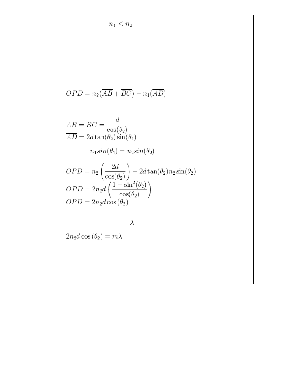
Consider light incident on a thin film and reflected by both the upper and lower
boundaries. The optical path difference (OPD) of the reflected light must be calculated in
order to determine the condition for interference. Referring to the ray diagram above,
the OPD between the two waves is the following:
Where,
Using Snell’s Law,
Interference will be constructive if the optical path difference is equal to an integer
multiple of the wavelength of light, .
This condition may change after considering possible phase shifts that occur upon
reflection.
8
Unit-02/Lecture-04
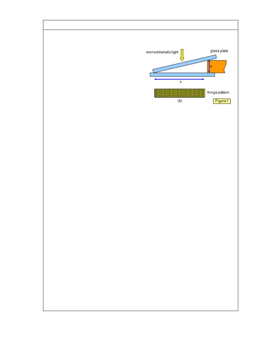
INTERFENCE IN WEDGE SHAPED FILMS
If two glass plates are placed face to face
with one end separated by a piece of tissue
paper or thin metal foil an air wedge will be
formed between them. If monochromatic
light is shone on the plates a series of
straight-line fringes will be seen parallel to
the line along which they touch (Figure 1).
This is due to interference by division of
amplitude, as with Newton’s rings. Some
light is reflected from the bottom surface of
the top plate and some from the top surface
of the bottom plate.
To see the fringes clearly the angle must be small, something like 4 minutes of arc. You
should also look for fringes close to the join of the plates where the air gap is smallest,
since the fringes are not well defined for path differences of more than some hundred
wavelengths (0.058 mm for sodium light – compare this with the thickness of a sheet of
paper).
Consider a point a distance x from the join. Path difference = 2e = 2xθ
where θ is the angle between the plates in radians (this angle is small, so tan θ = θ in
radians).
For an air wedge there is a phase change on reflection at the top surface of the lower
plate and so
2e = 2xθ=
mλ for a dark fringe
2e = 2xθ=
(
(2m+1)λ for a bright fringe
The travelling microscope or the eye must be focused close to the upper surface of the
air wedge since this is where the fringes are localised.
Pressing down gently with your finger on the plates will move the interference pattern,
since only a very small movement is needed to alter the path difference significantly.
The vertical soap film is a good example of wedge fringes. As the soap drains to the
bottom of the film a wedge of very small angle is formed. When the top part goes black
the film is about to break. The flatness of a glass surface may be tested by placing it on a
test surface which is known to be flat and illuminating them with monochromatic light;
any imperfections will show up as loop-shaped interference fringes around bumps or
depressions on the surfaces.
9
Unit-02/Lecture-05
MICHELSON INTERFEROMETER [RGPV/ June 2012 (7),Dec2013 (14)]
The
Michelson interferometer is the most common configuration for optical
interferometry and was invented by Albert Abraham Michelson. An interference pattern
is produced by splitting a beam of light into two paths, bouncing the beams back and
recombining them. The different paths may be of different lengths or be composed of
different materials to create alternating interference fringes on a back detector.
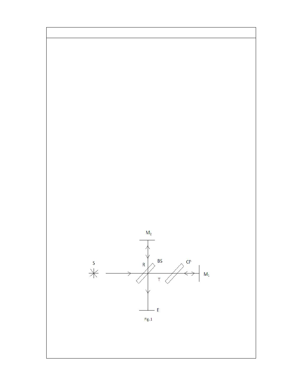
Construction
A Michelson interferometer consists of two highly polished mirrors M
1
& M
2
. A source S
emits monochromatic light that hits a half-silvered mirror, surface M, at point C. M is
partially reflective, so one beam is transmitted through to point B while one is reflected
in the direction of A. Both beams recombine at point C’ to produce an interference
pattern (assuming proper alignment) visible to the observer at point E. To the observer at
point E, the effects observed would be the same as those produced by placing surfaces A
and B’ (the image of B on the surface M) on top of each other.
Working
Light from a monochromatic source S is divided by a beam splitter (BS), which is oriented
at an angle 45° to the beam, producing two beams of equal intensity. The transmitted
beam (T) travels to mirror M
1
and it is reflected back to BS. 50% of the returning beam is
then reflected by the beam splitter and strikes the screen, E. The reflected beam (R)
travels to mirror M
2
, where it is reflected. 50% of this beam passes straight through
beam splitter and reaches the screen.
10
Since the reflecting surface of the beam splitter BS is the surface on the lower right, the
light ray starting from the source S and undergoing reflection at the mirror M
2
passes
through the beam splitter three times, while the ray reflected at M
1
travels through BS
only once. The optical path length through the glass plate depends on its index of
refraction, which causes an optical path difference between the two beams. To
compensate for this, a glass plate CP of the same thickness and index of refraction as
that of BS is introduced between M
1
and BS. The recombined beams interfere and
produce fringes at the screen E. The relative phase of the two beams determines
whether the interference will be constructive or destructive.
From the screen, an observer sees M
2
directly and the virtual image M
1
‘ of the mirror
M
1
, formed by reflection in the beam splitter, as shown in Fig. 3. This means that one of
the interfering beams comes from M
2
and the other beam appears to come from the
virtual image M
1
‘. If the two arms of the interferometer are equal in length, M
1
‘ coincides
with M
2
. If they do not coincide, let the distance between them be d, and consider a light
ray from a point S. It will be reflected by both M
1
‘ and M
2
, and the observer will see two
virtual images, S
1
due to reflection at M
1
‘, and S
2
due to reflection at M
2
. These virtual
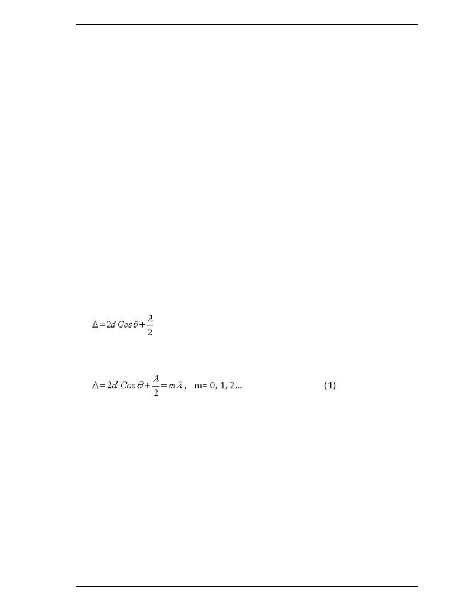
images will be separated by a distance 2d. If θ is the angle with which the observer looks
into the system, the path difference between the two beams is 2dcosθ. When the light
that comes from M
1
undergoes reflection at BS, a phase change of π occurs, which
corresponds to a path difference of λ/2.
Therefore, the total path difference between the two beams is,
The condition for constructive interference is then,
For a given mirror separation d, a given wavelength λ, and order m, the angle of
inclination θ is a constant, and the fringes are circular. They are called fringes of equal
inclination, or Haidinger fringes. If M
1
‘ coincides with M
2
, d = 0, and the path difference
between the interfering beams will be λ/2. This corresponds to destructive interference,
so the center of the field will be dark.
If one of the mirrors is moved through a distance λ/4, the path difference changes by λ/2
and a maximum is obtained. If the mirror is moved through another λ/4, a minimum is
obtained; moving it by another λ/4, again a maximum is obtained and so on. Because d is
multiplied by cosθ, as d increases, new rings appear in the center faster than the rings
already present at the periphery disappear, and the field becomes more crowded with
thinner rings toward the outside. If d decreases, the rings contract, become wider and
more sparsely distributed, and disappear at the center.
11
For destructive interference, the total path difference must be an integer number of
wavelengths plus a half wavelength,
If the images S
1
and S
2
from the two mirrors are exactly the same distance away, d=0 and
there is no dependance on θ. This means that only one fringe is visible, the zero order
destructive interfrence fringe, where
APPLICATION OF
MICHELSON’S INTERFEROMETER
i)Determination of wavelength of light
Using the Michelson interferometer, the wavelength of light from a monochromatic
source can be determined. If M
1
is moved forward or backward, circular fringes appear
or disappear at the centre. The mirror is moved through a known distance x and the
number n of fringes appearing or disappearing at the centre is counted. For one fringe to
appear or disappear, the mirror must be moved through a distance of λ/2. Knowing this,
we can write,
n λ=2x
so that the wavelength is
,
λ= 2x/n
ii) Difference between two close wavelengths:-
It works by taking a beam of light from a source and splitting it into 2, each beam of
equal intensity. A path difference of 2d is introduced to one beam, then both beams are
recombined at the beam splitter. The recombined beam is then reflected to an observer
and an interference pattern is observed.
For two monochromatic light sources, much like the sodium lamp used in this
experiment
dark fringes will occur when the optical path difference, d, is:

12
2d = m
1
λ
1
= m
2
λ
2
(1)
However this only applies when wavelength λ
1
≈ λ
2
and where m
1
and m
2
are integers.
From equation (1) the difference in wavelength can be obtained where:
∆λ=
λ
m
2
2∆𝑑𝑑
(2)
Where λ
m
is the mean wavelength of λ
1
, λ
2
and Δd is the mirror shit.
S.NO
RGPV QUESTIONS
Year
Marks
Q.1 Describe the construction and working of Michelson’s
interferometer. Explain the principle of formation of
circular fringes.
Dec
2013
7
Q.2 Describe Michelson’s interferometer and how will you
measure small difference in wavelengths of two waves with
Michelson’s interferometer. Calculate the distance between
the two successive positions of a movable mirror of
Michelson’s interferometer giving best fringes in the case of
sodium light having lines of wavelength 5890 A and 5896 A.
June
2012
14
13
UNIT 2/ LECTURE 6
NEWTON RINGS
[RGPV/ June 2013 (10)]
The phenomenon of Newton’s rings, named after Isaac Newton who first studied them
in 1717, is an interference pattern caused by the reflection of light between two
surfaces – a spherical surface and an adjacent flat surface. When viewed with
monochromatic light it appears as a series of concentric, alternating bright and dark
rings centered at the point of contact between the two surfaces. The light rings are
caused by constructive interference between the light rays reflected from both surfaces,
while the dark rings are caused by destructive interference
.
Construction and Theory
Rings are fringes of equal thickness. They are observed when light is reflected from a
plano-convex lens of a long focal length placed in contact with a plane glass plate. A
thin air film is formed between the plate and the lens. The thickness of the air film
varies from zero at the point of contact to some value t. If the lens plate system is
illuminated with monochromatic light falling on it normally, concentric bright and dark
interference rings are observed in reflected light. These circular fringes were discovered
by Newton and are called Newton’s rings.
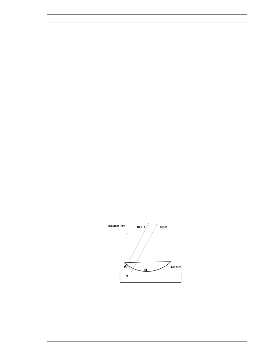
A ray AB incident normally on the system gets partially reflected at the bottom curved
surface of the lens (Ray 1) and part of the transmitted ray is partially reflected (Ray 2)
from the top surface of the plane glass plate. The rays 1 and 2 are derived from the
same incident ray by division of amplitude and therefore are coherent. Ray 2
undergoes a phase change of p upon reflection since it is reflected from air-to-glass
boundary.
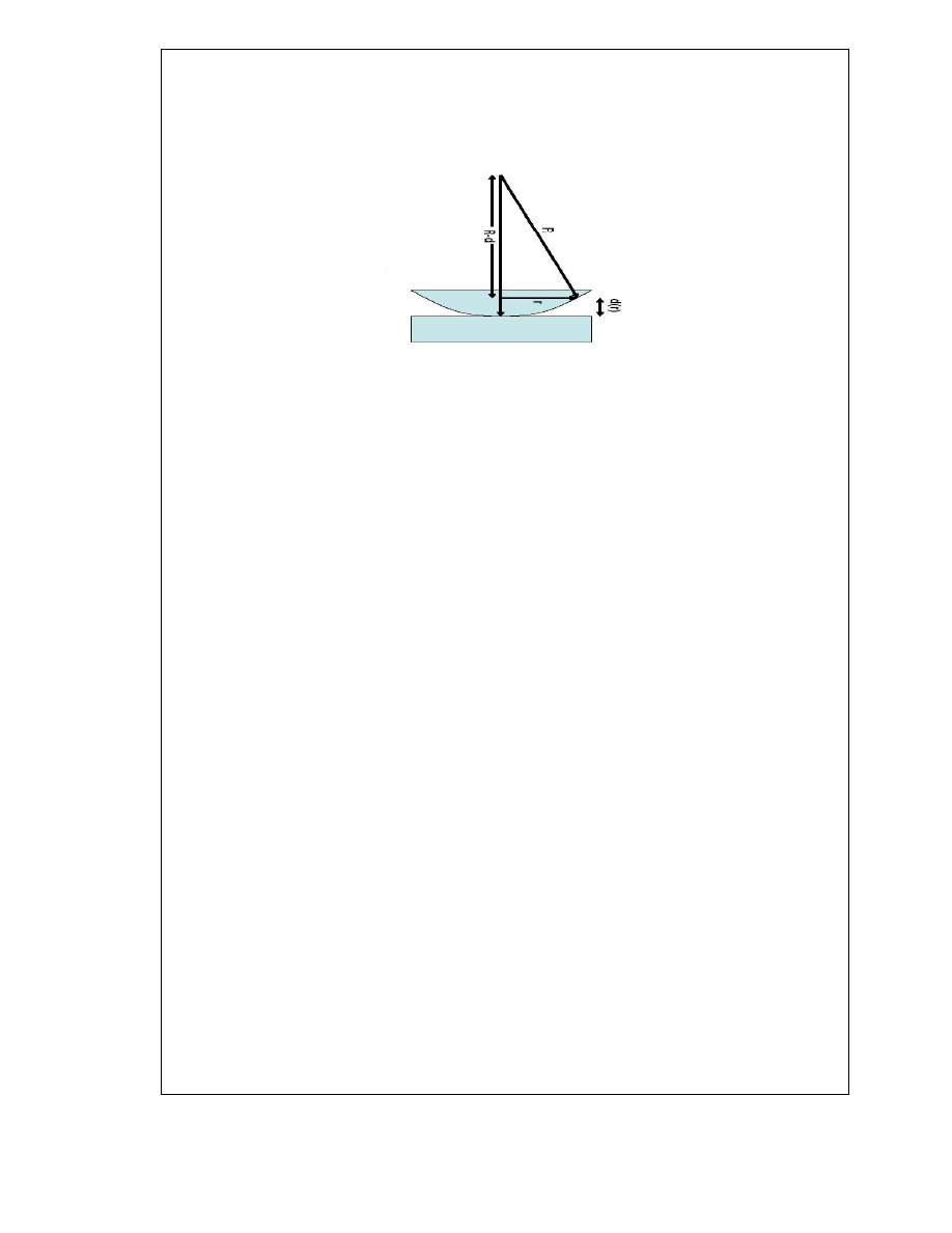
Determination of radius
Let the radius of curvature of the convex lens is
R and the radius of ring is ‘r‘. Consider
light of wave length ‘
l‘ falls on the lens. After partial refraction and partial reflection two
rays
1 and 2 are obtained. These rays interfere each other producing alternate bright
and dark rings. At the point of contact the thickness of air film is zero and the path
14
difference is also
zero and as a 180
O
path difference occurs, so they cancel each other and a dark ring is
obtained at the centre.
As we move away from the central point , path difference is also changed and alternate
dark and bright rings are obtained. Let us suppose that the thickness of air film is ‘
t‘.
By using the theorem of geometry,
BD x BE = AB x BC
r x r = t (2R-t)
r
2
=
2Rt – t
2
Since t is very small as compared to R , therefore t
2
should be neglected
r
2
= 2Rt
In thin films, path difference for constructive interference is:
2nt = (m+1/2) λ
Where n= refractive index
For air n = 1
Therefore,
2t = (m+1/2) λ ……….. (2)
For first bright ring m = 0
For second bright ring m = 1
For third bright ring m = 2
Similarly
For N
th
bright ring m = N-1
Putting the value of m in equation (2)
15
2t = (N-1+1/2) λ
2t = (N-1/2) λ
t =1/2 (N-1/2) λ ……… (3)
Putting the value of ‘t’ in equation (1)
r
2
= 2Rt
r
2
= 2R . 1/2 (N-1/2) λ
r
2
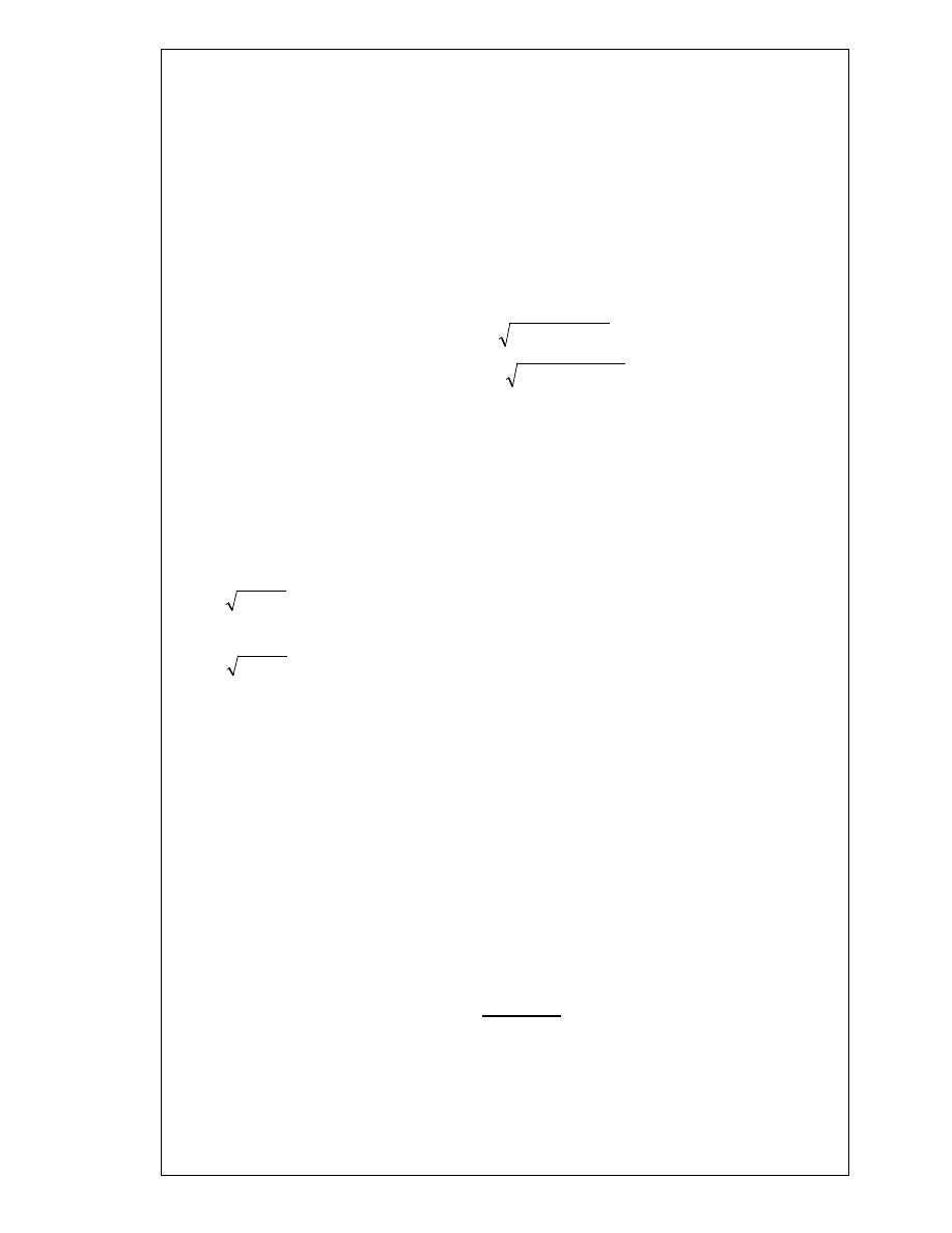
= R (N-1/2) λ
Thus the diameters of the bright rings are proportional to the square roots of odd
natural numbers
as (2N –1) is an odd number.
Similarly for a dark ring
2t=N λ
r
2
= 2R N λ
or D
2
= 4 N
λ
R
Thus diameters of dark rings are proportional to the square roots of natural numbers.
ITS APPLICATIONS
1. Determination of wavelength of light
Let D
n+p
and D
n
are the diameters of the (n+p)th ring and nth ring, where n & p be
integer numbers. then
D
2
n+p
= 4 (n+p)
λ
R
D
2
n
= 4 n
λ
R
On solving,
λ =
D
n+p
2
− D
n
2
4pR
)
2
/
1
(
−
=
N
R
r
n
λ
)
2
/
1
(
2
−
=
N
R
D
n
λ
N
R
r
n
λ
2
=
N
R
D
n
λ
4
=

16
2. Determination of refractive index of medium
Let D
n+p
and D
n
are the diameters of the (n+p)th ring and nth ring, where n & p be
integer numbers. then
for air
D
2
n+p
= 4 (n+p)
λ
R
D
2
n
= 4 n
λ
R
(D
2
n+p
– D
2
n
)
air
= 4 p
λ
R
For liquid
(D
2
n+p
)
liq
= 4 (n+p)
λ
R/
μ
(D
2
n
)
liq
= 4 n
λ
R/
μ
(D
2
n+p
– D
2
n
)
liq
= 4 p
λ
R/
μ
On solving,
µ =
(D
n+p
2
− D
n
2
)
air
(D
n+p
2
− D
n
2
)
liq
S.NO
RGPV QUESTION
YEAR
MARKS
Q.1
Give details of experimental
arrangement to produce Newton’s
rings by reflected Sodium light.
Prove that the diameter of bright
fringe is proportional to the square
root of add natural numbers.
June 2013
10
17
UNIT-2/LECTURE 7
Single slit diffraction [RGPV/ Dec2013 (7)]
A plane parallel light wave of wavelength λ is incident on a narrow slit of width e after
diffraction at slit, the bent rays superimpose to give intensity variation patches on
screen known as diffraction pattern. Some light encroaches into the shadow region
bound by slit openings. The intensity at the boundary of slit image on the screen has
fluctuations called diffraction fringes which can be mathematically investigated.
In order to find out intensity at p, draw a perpendicular AC on BR, the path difference
between secondary wavelets from A and B in direction θ
= BC = AB sinθ = e sinθ
Corresponding phase difference
= (2π/λ) .e sinθ
Let slit is divided in n parts then
(1/n) total phase = (1/n). (2π/λ) .e sinθ=d
Using the method of vector addition of amplitude R is given by
R = 𝑎𝑎
sin 𝑛𝑛 𝑑𝑑/2
sin 𝑑𝑑/2
= a sin(𝜋𝜋𝜋𝜋 sin 𝜃𝜃/𝜆𝜆)/sin(π 𝜋𝜋 sin 𝜃𝜃/𝑛𝑛𝜆𝜆)
= 𝑎𝑎
sin 𝛼𝛼
sin 𝛼𝛼/𝑛𝑛
= 𝑎𝑎
sin 𝛼𝛼
𝛼𝛼/𝑛𝑛
= na (sinα)/α
=A (sinα)/α
18
Thus the resultant amplitude is
R=A (sinα)/α
Now intensity
I= R
2
= A
2
[(sinα)/α]
2
I = I
o
[(sinα)/α]
2

19
S.NO
RGPV QUESTION
YEAR
MARKS
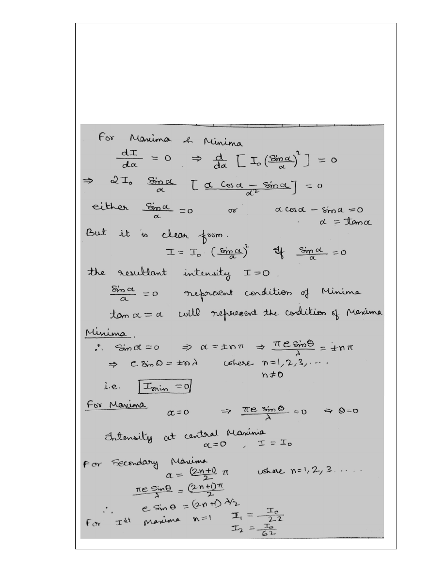
Q.1
Obtain an expression for maxima
and minima due to diffraction of
light by single slit
Dec 2013
7

20
UNIT 2/LECTURE 8
DIFFRACTION DUE TO PLANE DIFFRACTION GRATING (OR DIFFRACTION
DUE TO A NUMBER OF PARALLEL
EQUIDISTANT SLITS)
Construction.
A plane transmission grating is constructed by ruling a large number of fine, equidistant
and parallel lines on an optically plane glass plate with a diamond p in pen, The ruled
portion scatter S the light and thus acts like an opaque region. The unruled portion
transmits the light and thus works as transparent region. Thus we get alternate opaque
and transparent regions of equal widths and with equal separation. The width of the
transparent region becomes comparable to the wavelength of light and therefore the
diffraction of light takes place. A diffraction grating generally consists of 10000 to 50000
lines per inch.
Theory:-
Thus the diffraction grating is equivalent to N slits arrangement and the diffraction
pattern we obtain will be the combined diffraction effect of all such slits. Let’s e the
width of each slit and’d’that of opaque part between them, then (e + d) is known as
grating element. The diffracted rays from each of the slits are allowed to fall on a convex
lens which focus all of them at a point P on the screen As in the single slit, the waves
diffracted from each slit are equivalent to a single wave of amplitude,
R =
𝐴𝐴 𝑠𝑠𝑠𝑠𝑛𝑛𝛼𝛼
𝛼𝛼
(1)
Where
α =
𝜋𝜋 𝜋𝜋 𝑠𝑠𝑠𝑠𝑛𝑛𝜃𝜃
𝜆𝜆
(2)
The path difference between any two consecutive waves from two slits (e + d) sin θ.
Therefore, the corresponding phase difference will be
2𝜋𝜋
𝜆𝜆
(e+ d) sin θ. Since the
phasedifference is constant between any two consecutive waves it can be taken as
2𝜋𝜋
𝜆𝜆
(e+ d) sin θ = 2β
(3)
Thus we have to find out the resultant of N vibrations in a direction θ and each vibration
is of amplitude
𝐴𝐴 𝑠𝑠𝑠𝑠𝑛𝑛𝛼𝛼
𝛼𝛼
Similar to the resultant of n-harmonic waves, the resultant of N slits may be given as,
R’ =
𝑅𝑅 sin
2 𝑁𝑁 𝛽𝛽
2
sin
2𝛽𝛽
2
=
𝑅𝑅 sin 𝑁𝑁 𝛽𝛽
sin 𝛽𝛽
=
𝐴𝐴 𝑠𝑠𝑠𝑠𝑛𝑛𝛼𝛼
𝛼𝛼
sin 𝑁𝑁 𝛽𝛽
sin 𝛽𝛽
Thus the resultant intensity at P may be given as,
I = R’
2
=
𝐴𝐴
2
𝑠𝑠𝑠𝑠𝑛𝑛
2
𝛼𝛼
𝛼𝛼
2
𝑠𝑠𝑠𝑠𝑛𝑛
2
𝑁𝑁 𝛽𝛽
𝑠𝑠𝑠𝑠𝑛𝑛
2
𝛽𝛽
(4)

21
Here the factor
𝐴𝐴
2
𝑠𝑠𝑠𝑠𝑛𝑛
2
𝛼𝛼
𝛼𝛼
2
is the intensity factor due to a single slit while
𝑠𝑠𝑠𝑠𝑛𝑛
2
𝑁𝑁 𝛽𝛽
𝑠𝑠𝑠𝑠𝑛𝑛
2
𝛽𝛽
due to the
interference from all the N slits.
Principal maxima.
For maximum intensity, we have,
sinβ = 0
or
β = +_ nπ,
n = 0,1,2,……
But in this condition
sin 𝑁𝑁 𝛽𝛽
sin 𝛽𝛽
=
0
0
is in indeterminate form. Thus to find its value we have to
adopt the differential calculus procedure, according to which,
lim
𝛽𝛽→±𝑛𝑛𝜋𝜋
sin 𝑁𝑁 𝛽𝛽
sin 𝛽𝛽
= lim
𝛽𝛽→±𝑛𝑛𝜋𝜋
𝑑𝑑
𝑑𝑑𝛽𝛽
sin 𝑁𝑁 𝛽𝛽
𝑑𝑑
𝑑𝑑𝛽𝛽
sin 𝛽𝛽
= lim
𝛽𝛽→±𝑛𝑛𝜋𝜋
𝑁𝑁 cos 𝑁𝑁𝛽𝛽
cos 𝛽𝛽
= N
Thus,
I =
𝐴𝐴
2
𝑠𝑠𝑠𝑠𝑛𝑛
2
𝛼𝛼
𝛼𝛼
2
N
2
(5)
The intensity at these maxima is maximum and that is why it is principle maxima.
Therefore, the condition for principal maxima is
sin β = 0
or
β = ± nπ
or
𝜋𝜋
𝜆𝜆
(e+ d) sin θ = ± nπ
or
(e+ d) sin θ = ± nλ
(6)
For n=0, we get θ = 0, which gives the direction of the zero order principal maximum.
The values n=1, 2, 3…. correspond to the first, second, third…..order principal maxima.
Here the sign shows that the two principal maxima of the same order lie on either side
of zero order maximum.
Minima.
For sin N β = 0.But sin β ≠ 0
We get the minimum intensity. A series of minima, thus, obtained for
Nβ = ± mπ
or
N
𝜋𝜋
𝜆𝜆
(e+ d) sin θ = ± mπ
or
N (e+ d) sin θ = ±mλ
(7)
Thus for all integral values of m except 0, N, 2N, 3N,…..we get a minima, because for m=
O, N, 2N, 3N,…..the value of sin P = 0 and this will give the positions of principal maxima.
22
UNIT 2/LECTURE 9
RESOLVING POWER OF PLANE DIFFRACTION GRATING [RGPV/ Dec2012 (10)]
The resolving power of a grating is defined as the ratio of the wavelength of any spectral
line to the difference in wavelength between this line and a neighbouring line such that
two lines appear to be just resolved.
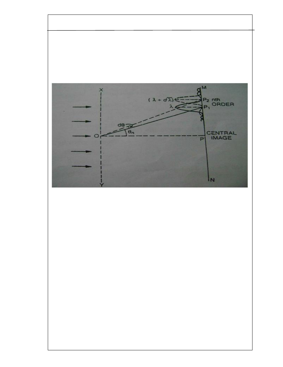
In above figure, XY is a grating surface and MN is the field of view of the telescope.P1 is
the nth primary maximum of a spectral line of wavelength λ at an angle of diffraction θn
. P2 is the nth primary maximum of a second spectral line of wavelength λ +dλ at a
diffracting angle of θn+dθ.P1 and P2 are the spectral lines in the nth order.
The direction of nth primary maximum for a wavelength λ is given by
(a + b) sin θn = n λ
(i)
The direction of nth primary maximum for a wavelength (λ+dλ) is given by
(a + b) sin(θn+dθ) = n (λ+dλ)
(ii)
The two lines will appear just resolved if the angle of diffraction (θn + dθ) also
corresponds to the direction of the first secondary minimum after the nth primary
maximum at P1. This is possible if the extra path difference introduced is λ /N where N is
the total number of lines of the grating surface.
Therefore
(a + b) sin (θn+dθ) = n λ + λ /N
(iii)
Equating the right hand sides of (ii) and (iii)
n (λ +d λ) = n λ + λ /N

23
λ/d λ =nN
The quantity λ /dλ = nN measures the resolving power of a grating.
S.NO
RGPV QUESTION
YEAR
MARKS
Q.1
Obtain the expression for
resolving power of plane
transmission grating.
Dec 2012
10
24
UNIT-2/ LECTURE 10
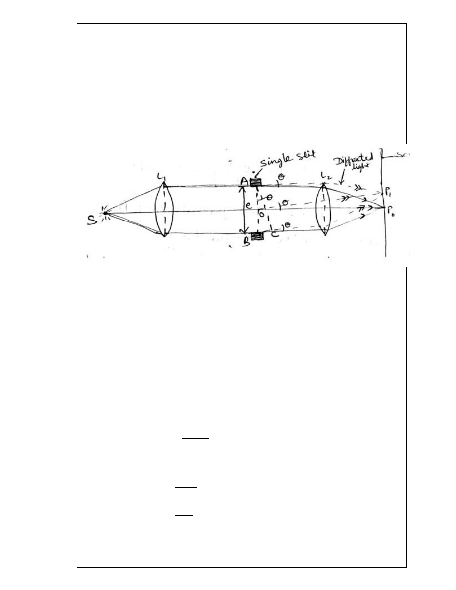
Prism Resolving Power
The term resolving power is applied to spectrographic devices using a prism or a grating.
Resolving power signifies the ability of the instrument to form separate spectral images of
two neighbouring wavelengths,
λ and λ + dλ in the wavelength region λ.
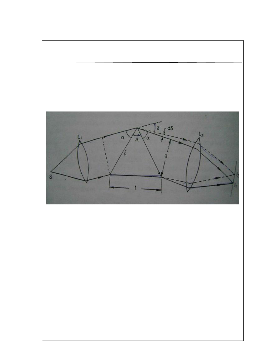
In fig. S is a source of light,
L
1
is a collimating lens and L
2
is the telescope objective. As the
two wavelengths λ and λ + dλ are very close, if the prism is set in the minimum deviation
position it would hold good for both the wavelengths. The final image
I
1
corresponds to
the principal maximum for wavelength
λ and image I
2
corresponds to the principal
maximum for wavelength, λ + dλ. I
1
and
I
2
are formed at the focal plane of the telescope
objective L
2
. The face of the prism limits the incident beam to a rectangular section of
width a. Hence, the Rayleigh criterion can be applied in the case of a rectangular aperture.
In the case of diffraction at a rectangular aperture, the position of
I
2
will correspond to the
first minimum of the image I
1
for wavelength λ
1
provided
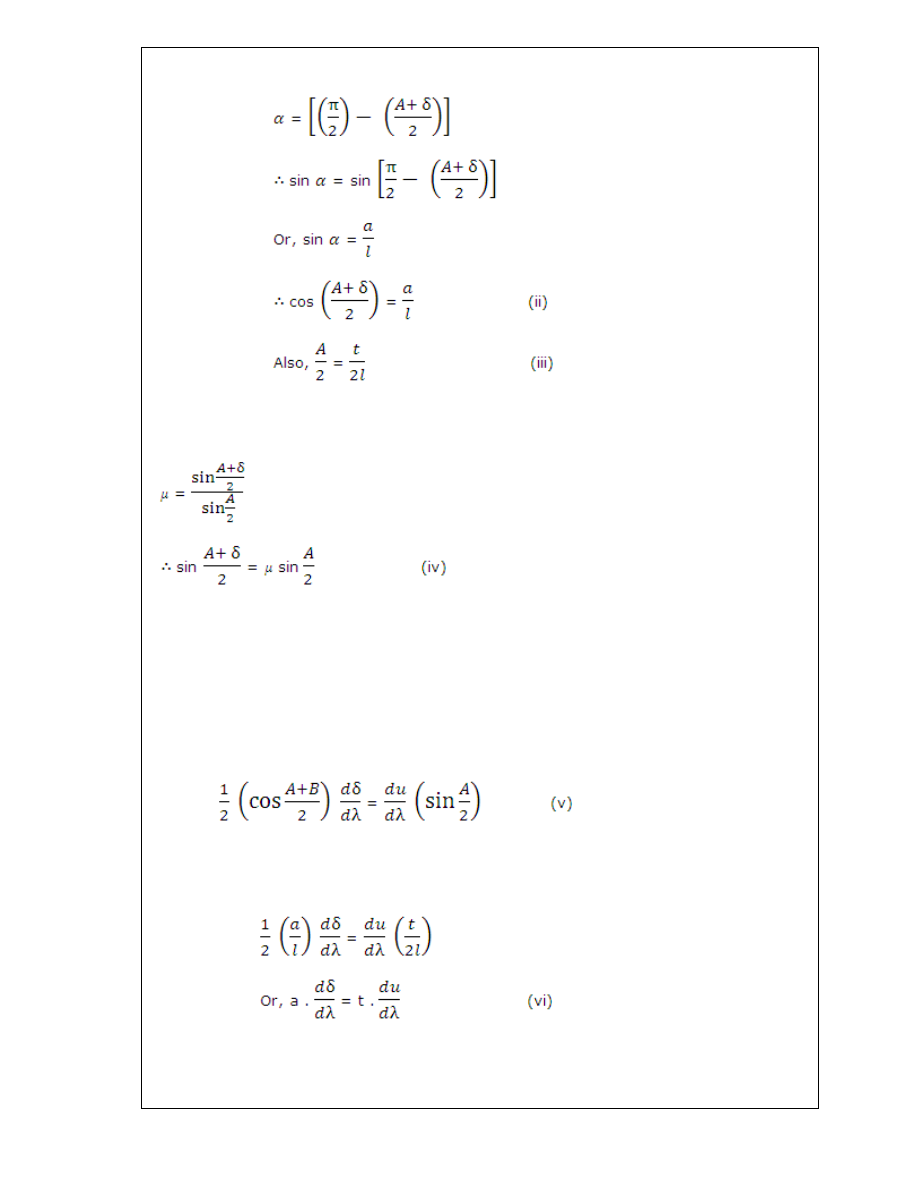
a.dδ = λ
or, dδ = λ/a (i)
Here, δ is the angle of minimum deviation for wavelength λ.
From the figure,
α+ A + α + δ = π
25
In the case of a prism
Here and δ are dependent on wavelength of light λ.
Differentiating equation (iv)
with respect to
Substituting the values from equations (ii) and (iii),
Substituting the value of dδ from equation (i),
26
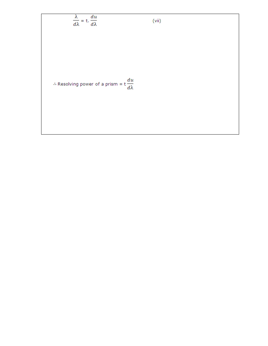
The expression λ/dλ measures the resolving power of the prism. It is defined as the ratio
of the wavelength of a spectral line to the difference in wavelength between the line and a
neighbouring line such that the two lines appear just resolved, according to Rayleigh’s
criterion.
Thus, the resolving power of a prism is
(i) directly proportional to the length of the base
and (ii) rate of change of refractive index with respect to wavelength for that particular
material.
27
UNIT 2/LECTURE 11
Concept of polarized light: [RGPV/Dec2011/(4)]
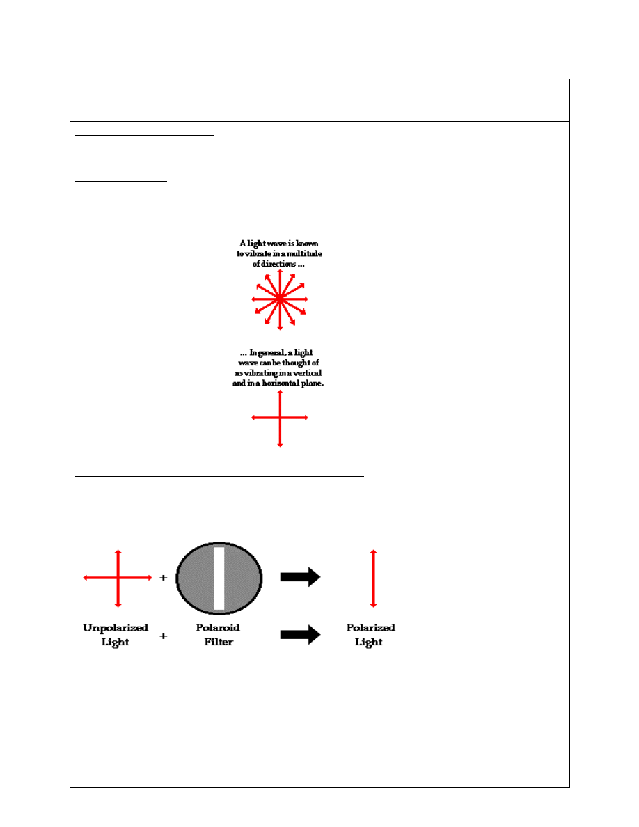
Unpolarized light: The ordinary light is also called unpolarized light, consist of very large
number of vibrations in all planes with equal probability at right angles to the direction of
propagation.
Linearly (Plane), circularly and elliptically polarized light
The light which has acquired the property of one sidedness is called polarized light. When the
vibrations are confined along a single direction at right angle to the direction of propagation of
light, then the light is called plane polarized light.
Light is an electromagnetic that vibrates at very high speed back and forth as it moves.
Individual light waves have their own wavelength as well as angle of vibration, which can range
through a full of 360°. The angle of vibration of a light wave is defined by its electric and
magnetic components (vectors) that are perpendicular to each other and to the direction of the
wave propagation. Ordinary visible light is unpolarized, i.e. it is composed of many different
waves vibrating in all directions. A plane electromagnetic wave is said to be
linearly polarized.
Circularly polarized light consists of two perpendicular electromagnetic plane waves of equal
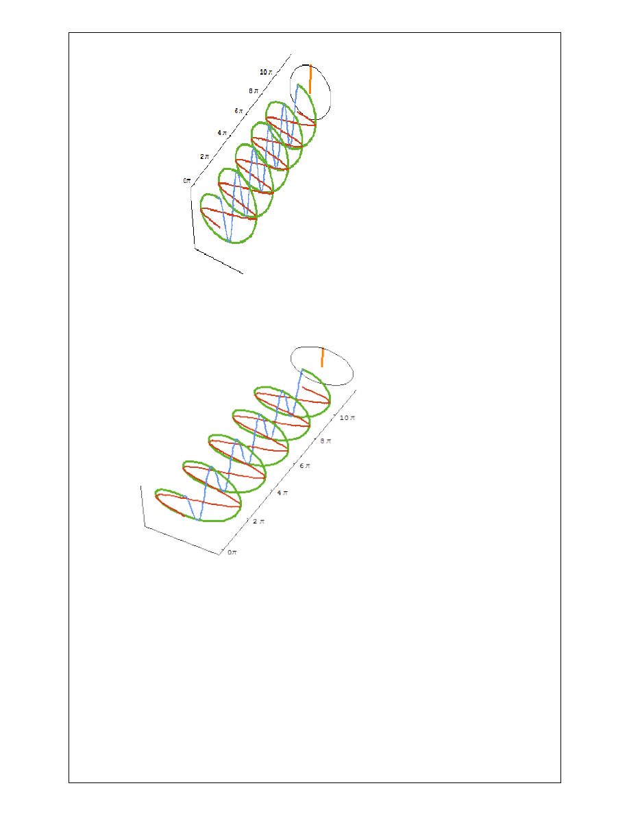
28
amplitude and 90° difference in phase.
Circularly polarized light
Elliptically polarized light consists of two perpendicular waves of unequal amplitude which differ
in phase by 90°
Elliptically Polarized light
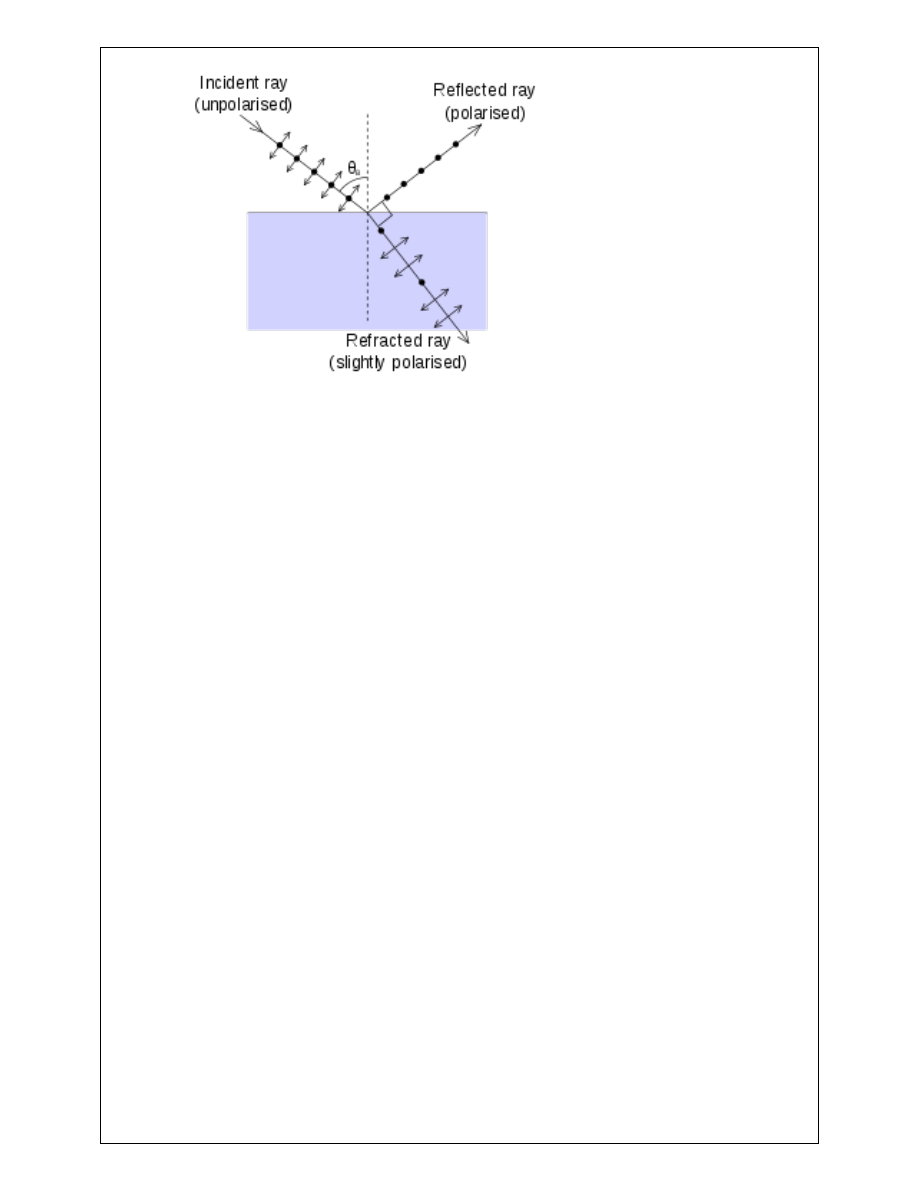
Brewsters Law : [RGPV/JUNE2013 (4)]
When ordinary light is reflected from the surface of transparent medium like glass or water it
becomes partly polarized. The degree of polarization changes with the angle of incidence. At a
particular angle of incidence the reflected light has the greatest percentage of polarized light
.The angle at which the reflected light is completely plane polarized, is known as angle of
polarization.
29
According to Brewster’s law “tangent of angle of polarization Θ
i
is numerically equal to the
refractive index µ of the medium”.
µ= tan Θ
i
From Brewster’s law
µ= tan Θ
i
——(i)
From Snell’s law
µ=sin Θ
i
/ sin r———(ii) (where r is angle of refraction)
tan Θ
i
= sin Θ
i
/ sin r
sinr= cos Θ
i
—————-(iii)
From fig.
r+ Θ
i
+Θ= 180 ——-(iv) (where Θ is angle between reflected ray and refracted
ray)
From equation (iii)
sin r=sin(90-Θ
i
)
sin r=sin(90-Θ
i
)
r= 90-Θ
i
r+ Θ
i
=90———-(v)
From equation (iv) and equation (v)
Θ=90°
Therefore we can say that reflected ray and refracted ray are at right angle to each other.

30
Plane of vibration and plane of Polarization
The plane which contains the direction of vibration of electric vector in plane polarized light is
called plane of vibration.
The plane perpendicular to the plane of vibration and passing through the direction of light is
called plane of polarization.
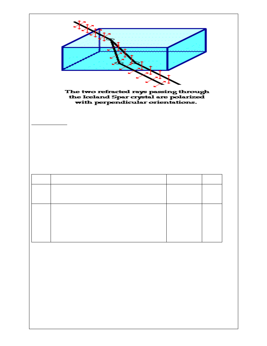
Double refraction and doubly refracting crystal
When a beam of light is allowed to pass through certain crystal, it splits in two refracting rays
instead of one, such crystals are called doubly refracting crystals and this phenomenon is known
as double refraction.
When unpolarized light enters in doubly refracting crystals it splits in two refracting rays:
1. Out of these two rays one ray obey the law obey the law of refraction (µ = sin 𝑠𝑠 / sin 𝑟𝑟),
is called ordinary ray, on the other hand other refracted ray does not obey law of
refraction is called extraordinary ray.
2. Inside the crystal the speed of both ordinary and extraordinary ray is same along the
optic axes and hence the refractive index of the crystal is also same along the optic axes
for both the rays (i.e. along optic axes v
o
=v
e
and µ
o
=µ
e
). Obviously if the light ray enter in
the crystal along optic axes there will no double refraction.
Types of doubly refracting crystals
On the basis of optic axes doubly refracting crystals are divided in following two
categories:-
1. Uniaxial Cryatals:- There is only one direction called optic axes along which refracted
beam travel with same velocity, such as Calcite, Tourmaline crystals.
2. Biaxial Crystals: – There are two directions along which the velocities of refracted beams
are same, such as Topaz, Argonite, and Mica.
31
Calcite Crystal: – It is hydrated calcium carbonate. It is colourless crystal which is transparent for
visible and ultraviolet light. In nature it is generally found in rhombohedral shape.
Its each face is a parallelogram with angle 102° and 78°. At the two diametrically opposite
corner three obtuse angle meet. These corners are called blunt corners. At the six remaining
corners of the crystal one obtuse and two acute angle meet. The optic axes of the crystal is
along that line passing through the blunt corners, which makes an equal angle with three faces.
S.NO. RGPV QUESTION
YEAR
MARKS
1
For a glass to air the critical angle of refraction is
40°. Calculate the angle of polarization for glass.
June2013
4
2
What is polarization of light? Distinguish between
plane, circularly and elliptically polarized light.
Explain the terms plane of polarization and plane of
vibration.
Dec 2011
14
32
Unit-02/Lecture-12
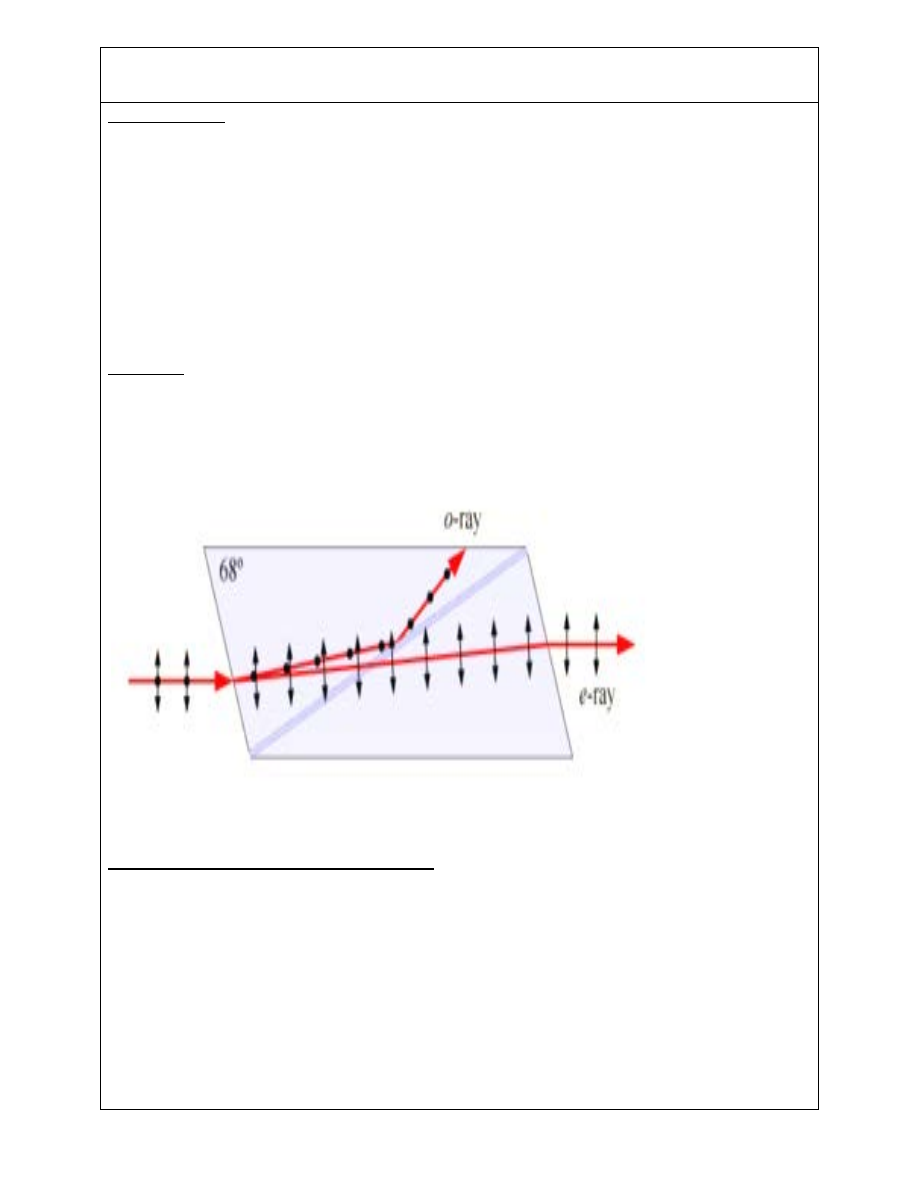
NICOL PRISM:- [RGPV/Dec2012(4),Dec2013(4)]
It is a special kind of prism made up of natural calcite crystal which is used to obtain plane
polarized light from unpolarized light and also used for the analysis of given light.
Nicol prism is constructed from a calcite crystal whose length is nearly 3 times of its width. The
end faces of crystal are cut down to reduce the angle in principle section to more acute angle of
68° instead of 78°. The crystal is then cut along the diagonal and two cut surfaces are after
polishing, are cemented back together with special cement called Canada Balsam, which is a
transparent substance. It is optically denser than Calcite for the extraordinary ray and less dense
for ordinary rays.
Working: A ray of light is incident on the surface of the Nicol prism splits into E-ray and O-ray
whose vibrations are respectively perpendicular and parallel to the principle section of Nicol
prism. The O-ray suffers total internal reflection at the Canada Balsam, surface for nearly normal
incidence because Canada Balsam is optically less dense for O-ray, while E- ray suffers refraction
at Canada Balsam surface as Canada Balsam is denser than calcite for E- ray.
Use of Nicol Prism as Polarizer and Analyzer
When two Nicol Prisms are arranged coaxially than the first Nicole Prism which produces plane
polarized light is known as Polarizer while the second which analyses the polarized light is
known as analyzer. When the two Nicol prisms are placed with their principle sections parallel
to each other, then the extraordinary ray transmitted by one is freely transmitted by the other.
If the second prism is gradually rotated, then the intensity of extraordinary ray gradually
decreases and when the two Nicol prisms are at right angle to each other i.e they are in crossed
position, no light comes from second prism. This is due to the fact that when the polarized
extraordinary ray enters the second Nicole prism, it acts as ordinary ray and totally internally
reflected. Therefore, the first Nicol prism produces plane polarized light and the second Nicol
prism analyses the light.

33
If a given light is examined through rotating Nicol prism and it shows a variation in intensity with
minimum intensity zero, the given light is plane polarized, and if intensity does not fall to zero
than the light is unpolarized light.
Retardation Plates
The crystal plates of doubly refracting crystal that retards the motion of one of the refracted
beams (O-ray and E-ray) are known as retardation plates.
These are of two types:
1. Half wave Plate
2. Quarter wave Plate
Half wave Plate : It is a crystal of plate of doubly refracting material whose thickness is such
that it introduces a phase difference of π or path difference of λ/2 between the ordinary ray and
extraordinary ray than it is called half wave plate.
𝑡𝑡 =
𝜆𝜆
2 (△µ)
Where t is thickness of plate, △= µ
e
-µ
o
or △= µ
o
-µ
e
Quarter wave Plate : It is a crystal of plate of doubly refracting material whose thickness is such
that it introduces a phase difference of π /2or path difference of λ/4between the ordinary ray
and extraordinary ray than it is called half wave plate.
𝑡𝑡 =
𝜆𝜆
4(△µ)
Where t is thickness of plate, △= µ
e
-µ
o
or △= µ
o
-µ
e
S.No.
Question
year
Marks
1
Discuss working of Nicol prism as Polarizer and
Analyzer.
Dec 2013 7
2
For a calcite, µ
o
=1.658and µ
e
=1.486 for sodium light
Of λ=5893A°. Calculate the minimum thickness of
quarter wave plate for calcite.
Dec 2012 4

34
Unit-02/Lecture-13
1. The distance between the slit and biprism and between biprism and screen are 50
cm each. The angle of biprism is 179°and its refractive index is 1.5. If the distance
between successive fringes is 0.0135cm, calculate the wavelength of light.
2. In a biprism experiment the distance between slit and screen is 160cm.The biprism is
40 cm away from the slit and its refractive index is 1.52. When a source of
wavelength 5893A is used the fringe width is found to be 0.01 cm. Find the angle of
prism.
3. A parallel beam of light λ= 5890A is incident on a thin glass plate µ=1.5 such that the
angle of refraction into the plate is 60°. Calculate the smallest thickness of the glass
plate which will appear dark by reflection.
4. In Newton’s rings experiment the diameter of the 10
th
dark ring is 0.433cm. Find the
wavelength of incident light, if the radius of curvature of the lens is 70cm.
5. A Newton’s rings arrangement is used with a source emitting two wavelengths
λ1=6000A and λ2=4500A and it is found that n
th
dark ring due to λ1 coincides with
the (n+1)th dark ring of λ2. If radius of curvature of curved surface is 90cm , find the
diameter of nth dark ring for λ1.
6. Newton’s rings are observed by keeping a spherical surface of 100cm radius on a
plane glass plate. If the diameter of the 16
th
bright ring is0.590cm what is the
wavelength if light used.
7. In Newton’s rings experiment, the diameter of the 4
th
and 12
th
dark rings is 0.400cm
and 0.700cm respectively. Find the diameter of 20
th
dark ring.
8. Newton’s rings are formed in reflected light of wavelength 6000a with a liquid
between the plane and curved surfaces. If the diameter of 6
th
bright ring is 3.1mm
and radius of curvature of the curved surface is 100cm calculate the refractive index
of the liquid.
9. In a Newton’s ring experiment the diameter of 10
th
ring changes from 1.40cm to
1.27cm when a liquid is introduced between the lens and plate. Calculate the
refractive index of the liquid.
10. The movable mirror of Michelson’s interferometer is moved through a distance of
0.02603mm. Find the number of fringes shifted across the cross-wire of the eyepiece
of the telescope. If the wavelength of 5206Ais used.
11. Calculate the distance between two successive positions of a movable mirror of a
Michelson’s interferometer giving best fringes in the case of sodium having lines of
wavelength 5890A and 5896A.
12. Light of wavelength 5500A falls normally on a slit of width 22000A. Calculate the
angular position of first two minima on either side of central maxima.
13. In a double slit diffraction pattern the screen is placed 170cm away from slit. The

35
width of the slits is 0.08mm and they are 0.4mm apart. Calculate the wavelength of
light if the fringe width is 0.25cm. Also find the missing order.
14. How many lines are there on a grating if the angle of diffraction is 20° for the first
order, when light of wavelength 600nm is incident on the grating normally.
15. How many orders will be visible if the wavelength of the incident radiation is 5000A
and the number of lines on the grating is 2620in one inch?
16. In a fraunhoffer diffraction pattern of a n slit , it is found that the forth secondary
maxima is missing. What is the ratio of the slit width to the slit separation?
17. If two spectral lines of wavelength 5890A and 5896A are to be seen just separated in
the first order spectrum of the grating, find the number of lines in the grating.
18. A grating has 15cm of the surface ruled with 6000 lines per cm what is the resolving
power of grating in the first order.
19. What must be minimum number of lines per cm in a half inch width grating to
resolve the D1 and D2 lines of sodium.
20. In relation to a plane transmission grating with 5000 lines per cm answer the
following:
21. For wavelength 6000A what is the highest order of spectrum which may be
observed.
22. If opaque spaces are exactly two times transparent spaces, which order of spectra
will be absent?
23. 21 Calculate the Brewster’s angles for the following liquids Ethyl alcohols for which
µ=1.361 and Carbon tetrachloride for which µ=1.461.
24. 22 A glass plate is to be used as a polarizer. Find the angle of polarization for it . Also
find angle of refraction. Give µ for glass 1.54.
25. 23 Calculate the thickness of a quarter wave plate made of quartz to be used with
sodium light λ=6000A µo=1.544 and µe=1.533.
26. 24 Determine the thickness of a crystal plate of calcite which can produce circular
polarized light. For calcite µe= 1.486 and µo=1.658 and λ=5893A.
27. 25 Calculate the minimum thickness of a plate if the ordinary and extra ordinary rays
coming out mix up from plane polarized light given λ=6000A µo=1.562 and
µe=1.552.