Asynchronous vs. Synchronous Transmission Notes
Asynchronous vs. Synchronous Transmission
Serialized data is not generally sent at a uniform rate through a channel. Instead, there is usually a burst of regularly spaced binary data bits followed by a pause, after which the data flow resumes. Packets of binary data are sent in this manner, possibly with variable-length pauses between packets, until the message has been fully transmitted. In order for the receiving end to know the proper moment to read individual binary bits from the channel, it must know exactly when a packet begins and how much time elapses between bits. When this timing information is known, the receiver is said to be synchronized with the transmitter, and accurate data transfer becomes possible. Failure to remain synchronized throughout a transmission will cause data to be corrupted or lost.Two basic techniques are employed to ensure correct synchronization. In synchronous systems, separate channels are used to transmit data and timing information. The timing channel transmits clock pulses to the receiver. Upon receipt of a clock pulse, the receiver reads the data channel and latches the bit value found on the channel at that moment. The data channel is not read again until the next clock pulse arrives. Because the transmitter originates both the data and the timing pulses, the receiver will read the data channel only when told to do so by the transmitter (via the clock pulse), and synchronization is guaranteed.
Techniques exist to merge the timing signal with the data so that only a single channel is required. This is especially useful when synchronous transmissions are to be sent through a modem. Two methods in which a data signal is self-timed are nonreturn-to-zero and biphase Manchester coding. These both refer to methods for encoding a data stream into an electrical waveform for transmission.
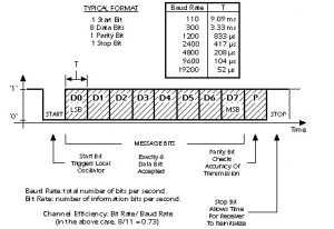
In asynchronous systems, a separate timing channel is not used. The transmitter and receiver must be preset in advance to an agreed-upon baud rate. A very accurate local oscillator within the receiver will then generate an internal clock signal that is equal to the transmitter’s within a fraction of a percent. For the most common serial protocol, data is sent in small packets of 10 or 11 bits, eight of which constitute message information. When the channel is idle, the signal voltage corresponds to a continuous logic ‘1′. A data packet always begins with a logic ‘0′ (the start bit) to signal the receiver that a transmission is starting. The start bit triggers an internal timer in the receiver that generates the needed clock pulses. Following the start bit, eight bits of message data are sent bit by bit at the agreed upon baud rate. The packet is concluded with a parity bit and stop bit. One complete packet is illustrated below:
The packet length is short in asynchronous systems to minimize the risk that the local oscillators in the receiver and transmitter will drift apart. When high-quality crystal oscillators are used, synchronization can be guaranteed over an 11-bit period. Every time a new packet is sent, the start bit resets the synchronization, so the pause between packets can be arbitrarily long. Note that the EIA232 standard defines electrical, timing, and mechanical characteristics of a serial interface. However, it does not include the asynchronous serial protocol shown in the previous figure, or the ASCII alphabet described next.
Parity and Checksums
Noise and momentary electrical disturbances may cause data to be changed as it passes through a communications channel. If the receiver fails to detect this, the received message will be incorrect, resulting in possibly serious consequences. As a first line of defense against data errors, they must be detected. If an error can be flagged, it might be possible to request that the faulty packet be resent, or to at least prevent the flawed data from being taken as correct. If sufficient redundant information is sent, one- or two-bit errors may be corrected by hardware within the receiver before the corrupted data ever reaches its destination.
A parity bit is added to a data packet for the purpose of error detection. In the even-parity convention, the value of the parity bit is chosen so that the total number of ‘1′ digits in the combined data plus parity packet is an even number. Upon receipt of the packet, the parity needed for the data is recomputed by local hardware and compared to the parity bit received with the data. If any bit has changed state, the parity will not match, and an error will have been detected. In fact, if an odd number of bits (not just one) have been altered, the parity will not match. If an even number of bits have been reversed, the parity will match even though an error has occurred. However, a statistical analysis of data communication errors has shown that a single-bit error is much more probable than a multibit error in the presence of random noise. Thus, parity is a reliable method of error detection.
Another approach to error detection involves the computation of a checksum. In this case, the packets that constitute a message are added arithmetically. A checksum number is appended to the packet sequence so that the sum of data plus checksum is zero. When received, the packet sequence may be added, along with the checksum, by a local microprocessor. If the sum is nonzero, an error has occurred. As long as the sum is zero, it is highly unlikely (but not impossible) that any data has been corrupted during transmission.
Errors may not only be detected, but also corrected if additional code is added to a packet sequence. If the error probability is high or if it is not possible to request retransmission, this may be worth doing. However, including error-correcting code in a transmission lowers channel efficiency, and results in a noticeable drop in channel throughput.
Data Compression
If a typical message were statistically analyzed, it would be found that certain characters are used much more frequently than others. By analyzing a message before it is transmitted, short binary codes may be assigned to frequently used characters and longer codes to rarely used characters. In doing so, it is possible to reduce the total number of characters sent without altering the information in the message. Appropriate decoding at the receiver will restore the message to its original form. This procedure, known as data compression, may result in a 50 percent or greater savings in the amount of data transmitted. Even though time is necessary to analyze the message before it is transmitted, the savings may be great enough so that the total time for compression, transmission, and decompression will still be lower than it would be when sending an uncompressed message.Some kinds of data will compress much more than others. Data that represents images, for example, will usually compress significantly, perhaps by as much as 80 percent over its original size. Data representing a computer program, on the other hand, may be reduced only by 15 or 20 percent.
A compression method called Huffman coding is frequently used in data communications, and particularly in fax transmission. Clearly, most of the image data for a typical business letter represents white paper, and only about 5 percent of the surface represents black ink. It is possible to send a single code that, for example, represents a consecutive string of 1000 white pixels rather than a separate code for each white pixel. Consequently, data compression will significantly reduce the total message length for a faxed business letter. Were the letter made up of randomly distributed black ink covering 50 percent of the white paper surface, data compression would hold no advantages.